| HSS Blade | Carbide Blade | HSS or Carbide |
| ||||||||
ISO | Material | Condition | As is | vc cutting speed (1) | vc cutting speed (1) | ƒr cutting feed(1) | Recommended Chip-former | Coolant | ||||
AISI / SAE / ASTM | DIN W.-Nr. | Uncoated m/min. sfm | Coated m/min. sfm | Coated m/min. sfm | Coated/Uncoated mm/rev ipr | |||||||
P | Non-alloy steel and cast steel, free cutting steel | <0.25% C | Annealed | 1020 | 1.0044 | 25-45 80-150 | 45-65 100-165 | 60-120 200-390 | 0.08-0.20 0.003-0.008 | 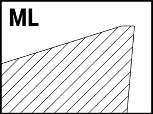 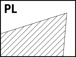 | Air / Wet | |
≥0.25% C | Annealed | 1035 | 1.0501 | |||||||||
<0.55% C | Quenched and tempered | 1045 | 1.1201 | |||||||||
≥0.55% C | Annealed | 1055 | 1.0535 | |||||||||
Quenched and tempered | 1060 | 1.1221 | ||||||||||
Low alloy and cast steel (less than 5% of alloying elements) | Annealed | G92600 | 1.5028 | 20-45 80-150 | 35-65 115-165 | 50-120 165-390 | 0.08-0.20 0.003-0.008 | |||||
Quenched and tempered | 4130 | 1.7218 | ||||||||||
4142 | 1.2332 | |||||||||||
5045 | 1.7006 | 20-40 65-130 | 35-55 115-180 | 50-100 165-330 | ||||||||
High alloyed steel, cast steel and tool steel | Annealed | H13 | 1.2344 | 15-35 50-115 | 30-50 100-165 | 45-90 150-295 | 0.08-0.15 0.003-0.006 | |||||
Quenched and tempered | M33 | 1.3249 | ||||||||||
Stainless steel and cast steel | Ferritic/martensitic | 420 | 1.4021 | |||||||||
Martensitic | ||||||||||||
M | Stainless steel | Austenitic, duplex | 304L | 1.4306 | 15-30 50-100 | 30-55 100-180 | 50-100 165-330 | 0.08-0.15 0.003-0.006 | | Wet | ||
K | Gray cast iron (GG) | Ferritic / pearlitic | Class 25 | 0.6015 | 20-35 65-115 | 35-55 115-180 | 60-120 200-395 | 0.08-0.25 0.003-0.012 | | Air / Wet | ||
Pearlitic / martensitic | Grade H20 | 036037 | ||||||||||
Nodular cast iron (GGG) | Ferritic | 60-40-18 | 0.7043 | 30-70 100-230 | 40-90 130-295 | 50-100 165-330 | 0.08-0.20 0.005-0.008 | |||||
Pearlitic | F33500 | 0.7050 | ||||||||||
Malleable cast iron | Ferritic | A47 | 0.8135 | |||||||||
Pearlitic | A220 Class | 0.8155 | ||||||||||
N | Aluminum-wrought alloys | Not hardenable | 5005 | 3.3315 | 50-70 165-230 | 75-120 245-395 | 100-160 330-525 | 0.10-0.30 0.004-0.012 |
| Wet | ||
Hardenable | 7075 | 3.4365 | ||||||||||
Aluminum-cast alloys | ≤12% Si | Not hardenable | 518.0 | 3.3292 | ||||||||
Hardenable | 515.0 | 3.3241 | ||||||||||
>12% Si | High temperature | 390 |
| |||||||||
Copper alloys | >1% Pb | Free cutting | C36000 | 2.0375 | 30-60 100-200 | 45-100 150-330 | 90-130 295-425 | |||||
| Brass | C22000 | 2.0230 | |||||||||
Electrolytic copper | C63000 | 2.0966 | ||||||||||
Non metallic | Duroplastics, fiber plastics | Bakelite |
| 60-100 195-330 | 90-150 295-490 | 180-305 600-1000 | ||||||
Hard rubber | Ebonite |
| ||||||||||
S | High temperature alloys | Fe based | Annealed | 330 | 1.4864 | 10-15 33-50 | 15-35 50-115 | 40-80 130-260 | 0.10-0.20 0.005-0.008 | |
Wet | |
Hardened | S590 | 1.4977 | ||||||||||
Ni or Co based | Annealed | Incoloy 825 | 2.4858 | Not recommended | 10-15 33-50 | 25-40 80-130 | ||||||
Hardened | Inconel 718 | 2.4668 | ||||||||||
Cast | Nimocast K24 | 2.4674 | ||||||||||
Titanium alloys | Pure | Titanium G.1 | 3.7024 | 10-15 33-50 | 15-20 50-65 | 30-60 100-180 | ||||||
Alpha+beta alloys, hardened | Titanium G.5 | 3.7165 | ||||||||||
H | Hardened steel | Hardened | HARDOX 500 |
| Not recommended | 10-20 10-20 30-65 | 30-50 100-165 |
0.04-0.06 0.0015-0.0024 |
| Air | ||
Hardened | HARDOX Extreme |
| 10-15 30-50 | 30-40 100-130 | ||||||||
Chilled cast iron | Cast | A532 lllA 25% Cr | 0.9650 | 15-20 50-65 | 45-50 145-165 | |||||||
Cast iron | Hardened | A532 IID 20% CrMo | 0.9645 | 10-20 30-65 | 30-50 100-165 | |||||||
C | Carbon Fiber reinforced plastics (CFRP) | Cured |
– | Not recommended | 90-140 295-460 | 0.05-0.25 0.002-0.010 |
| Air / Wet | ||||
Glass Fiber reinforced plastics (GFRP) | 90-350 295-1150 | |||||||||||
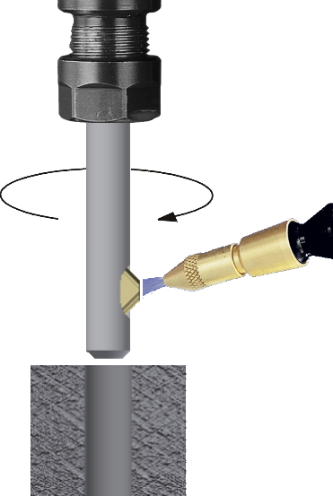
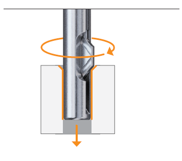
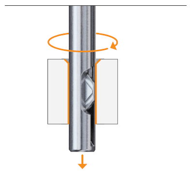
- Tool Rotation and Coolant: The UBURR family of tools is suitable for right-hand machining with clockwise tool rotation and should be used with external coolant to flush away chips and swarf from the cutting zone, as shown in Figure 1.
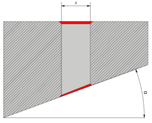
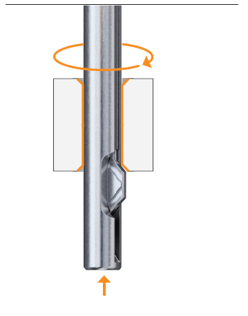
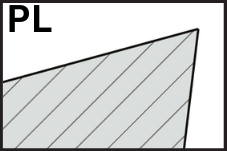
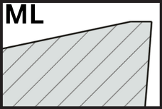
- Geometrical Limitations for Inclined and Cylindrical Surfaces:
- For inclined surfaces (Figure 2), the maximum inclination angle depends on the pilot-hole diameter and can be calculated using the following formula:
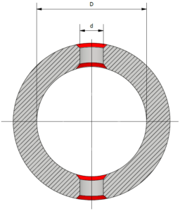
- For tubes (Figure 3), it is necessary to ensure that the tool diameter is suitable for the application. This can be verified using the following formula:
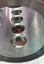
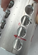
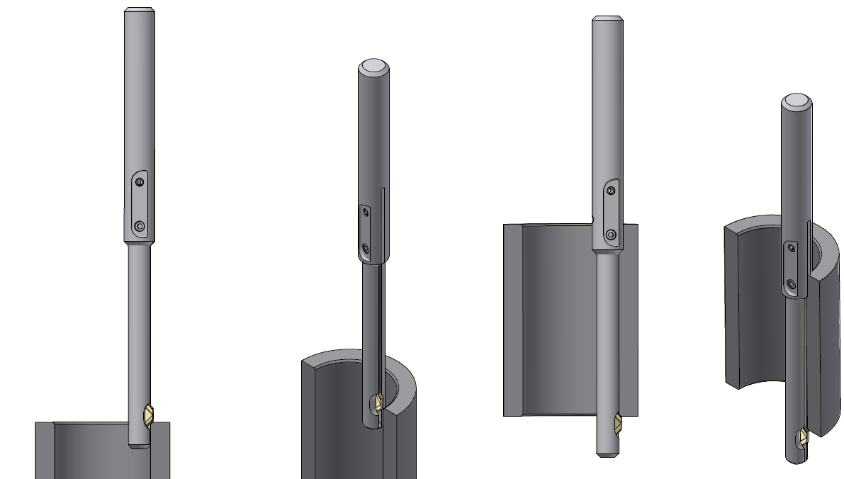
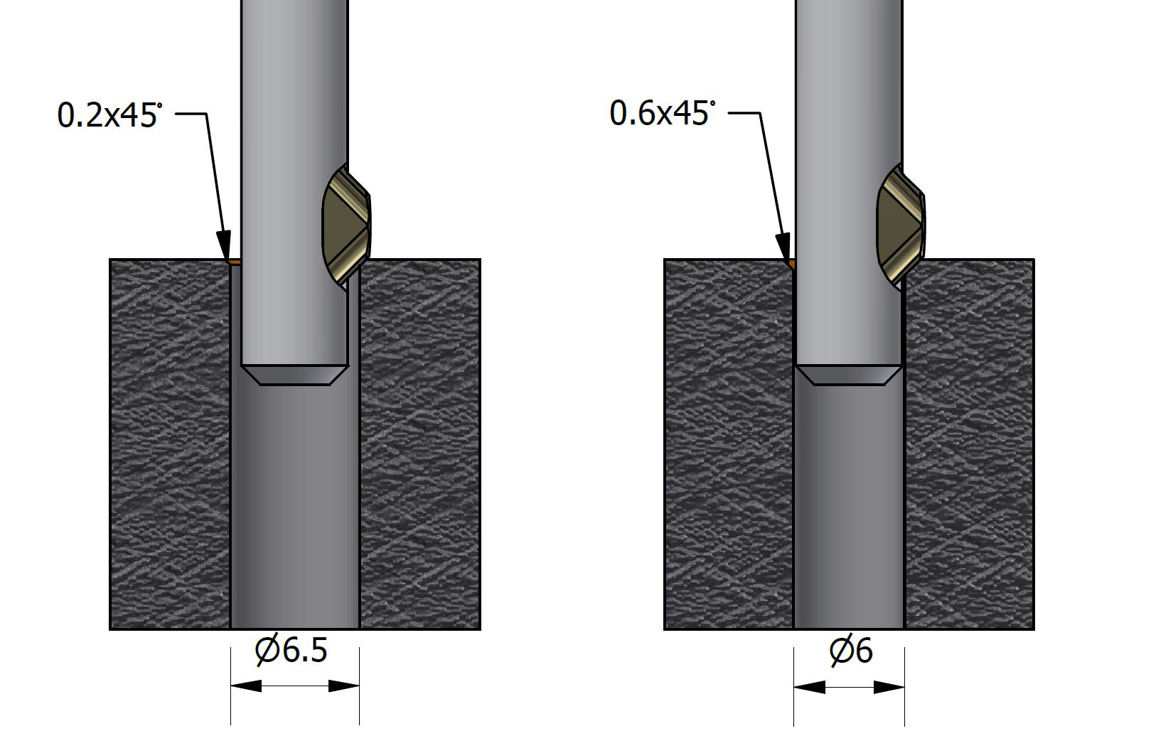
- When machining on sloped or cylindrical surfaces, an uneven chamfer will naturally form as illustrated in the accompanying images: