
Surface Brush Machining Guidelines and Safety Instructions
Features:
- Designed for surface polishing and deburring.
- Ideal for achieving uniform finishes on flat surfaces.
- The brushes are designed to fit into a sleeve with the tool shank, making them ideal for automated deburring in CNC machines, robots and machining centers.
- Made from ceramic fiber, it removes burrs using the cutting edges of the fibers.
- Can Function as a cross-hole tool, using centrifugal force during rotation for effective deburring.
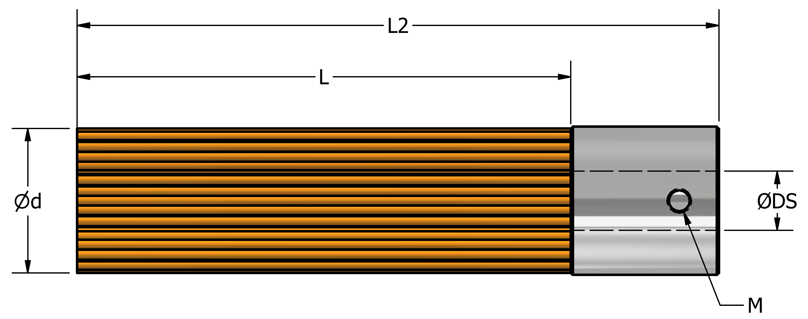
Surface Brush Product Range, Speeds and Feeds:
|
Brush |
Ød mm |
ØDS mm |
L mm |
L2 mm |
Spare Parts (1) |
Weight gram |
Depth Of Cut (DOC) |
Recommended R.P.M. |
Feed (max.) mm/min. |
Brush (2) mm |
|||||
|
Clamping Screw |
SKU# |
LN Key |
SKU# |
Polishing |
Deburring |
Max. |
|||||||||
|
mm |
mm |
mm |
|||||||||||||
|
Ø6 /0.236″ |
Ø6 |
N/A |
30 |
42.5 /1.673″ |
N/A |
N/A |
N/A |
N/A |
3.0 |
0.2 |
0.5 |
1.2 |
9000-12000 |
2000 |
10 |
|
Ø15 /0.590″ |
Ø15 |
6 |
50 |
65 |
M3*0.5*4 |
UF0019 |
1.5 |
DH0005 |
7.0 |
5700-7200 |
|||||
|
Ø25 /0.984″ |
Ø25 |
9 |
75 |
100 |
M4*0.7*8 |
UF0018 |
2.0 |
UF0020 |
21.0 |
5000-6000 |
|||||
|
Ø40 /1.575″ |
Ø40 |
12 |
75 |
96 |
M6*1.0*16 |
UF0017 |
3.0 |
DB0007 |
26.0 |
2700-3600 |
|||||
|
Ø60 /2.362” |
Ø60 |
13 |
75 |
96 |
M6*1.0*20 |
UF0016 |
3.0 |
DB0007 |
70.0 |
1800-2400 |
|||||
|
Ø100 /3.937″ |
Ø100 |
16 |
75 |
97 |
M6*1.0*25 |
UF0015 |
3.0 |
DB0007 |
140.0 |
1000-1400 |
|||||
(1)The surface brush comes with 2 set-screws for mounting a shaft. For more details, see “Versatile Surface Brush for Efficient Cross-Hole Burr Removal” below.
(2)When mounted with corresponded sleeve.
Mounting Options Surface Brushes:
Mounting the Surface Brush into a standard tool holder—such as a collet or chuck—for use with CNC machines and robotic arms can be done in two ways:
With Sleeves:
The sleeve reinforces the base of the brush, providing enhanced stability during high-speed rotation. This ensures precise and consistent contact with the workpiece, allowing for greater grinding pressure and improved performance.
Without Sleeves:
Use the appropriate shank size as specified by the ØDS parameter in the table above. Make sure to use the correct spare parts, including the clamping screw and LN key.
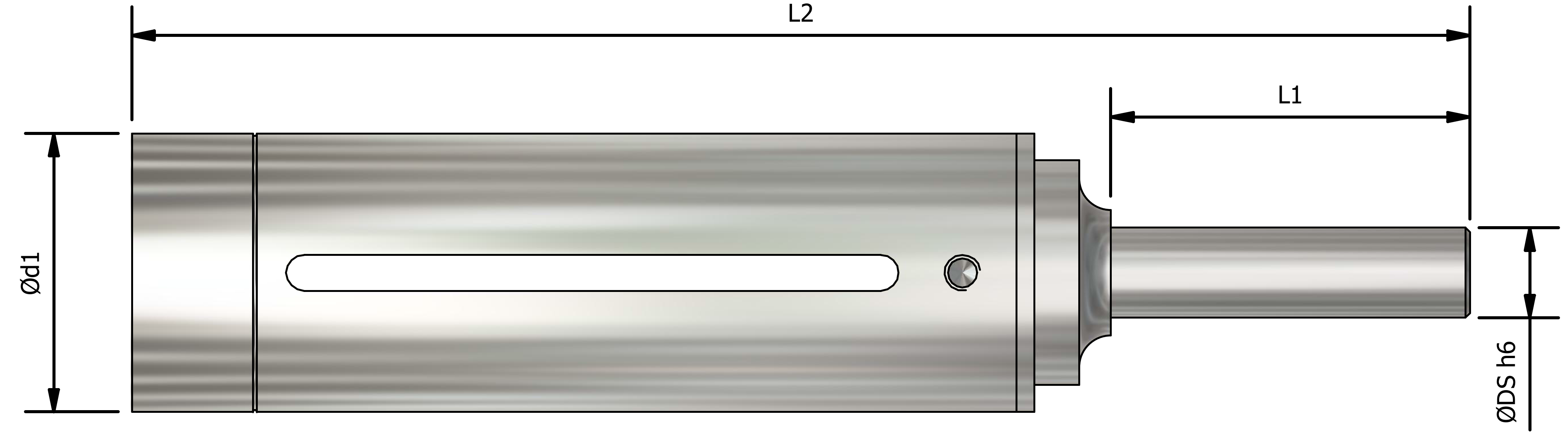
Face Brush Sleeves Item List and Spare Parts:
|
Surface Brush |
SKU# |
Description |
Ød1 external mm /Inch |
ØDS mm /Inch |
L1 mm /Inch |
L2 mm /Inch |
Weight gram |
Sleeve Spare Parts |
|||
|
Clamping Screw M*P*Length (mm) |
SKU# |
LN Key S (mm) |
SKU# |
||||||||
|
Ø6 /0.236″ |
UF5506 |
UF-FS-6-C06-L70 |
10 /0.394” |
Ø6 /0.236″ |
30 /1.181″ |
71 /2.795″ |
30 |
M3*0.5*4 |
UF0010 |
2.5 |
UF0021 |
|
Ø15 /0.590″ |
UF5515 |
UF-FS-15-C06-L90 |
18.5 /0.728” |
Ø6 /0.236″ |
30 /1.181″ |
92 /3.622″ |
40 |
M3*0.5*6 |
UF0011 |
2 |
UF0020 |
|
Ø25 /0.984″ |
UF5525 |
UF-FS-25-C10-L140 |
30 1.181” |
Ø10 /0.394″ |
30 /1.181″ |
149 /5.866″ |
160 |
M4*0.7*10 |
UF0012 |
2.5 |
UF0021 |
|
Ø40 /1.575″ |
UF5540 |
UF-FS-40-C12-L140 |
45 /1.772” |
Ø12 /0.472″ |
30 /1.181″ |
135 5.315″ |
200 |
M6*1.0*10 |
UF0013 |
4 |
UF0022 |
|
Ø60 /2.362” |
UF5560 |
UF-FS-60-C12-L145 |
67 /2.638” |
Ø12 /0.472″ |
40 /1.575″ |
145 /5.708″ |
320 |
M6*1.0*10 |
UF0013 |
4 |
UF0022 |
|
Ø100 /3.937″ |
UF5500 |
UF-FS-100-C16-L155 |
110 /4.330” |
Ø16 /0.630″ |
40 /1.575″ |
155 /6.102″ |
670 |
M8*1.25*16 |
UF0014 |
5 |
UF0023 |
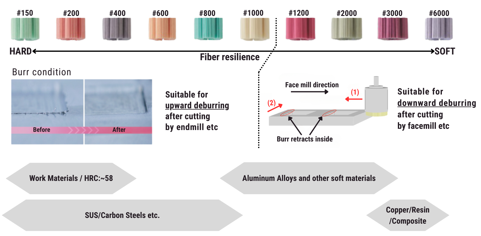
Grit Selection by Burr Condition & Material
How to Use the UFIBER Surface Brush:
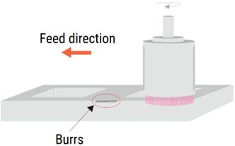
1. Feed direction
To remove side burrs, use a fiber brush with the up-cut method, where the brush pushes upward against the burrs from underneath.
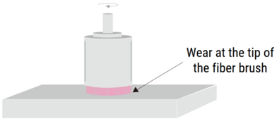
2. Brush projection adjustment
As the fiber brush wears down, it becomes less flexible and more rigid, increasing the cutting tension.
it’s important to adjust the tool’s length for prolonged use.
Please adjust the cutting conditions accordingly.
If the sleeve interferes with the work surface, adjust the brush’s projection accordingly.
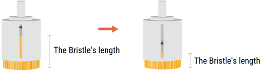
When the bristles are long, they maintain flexibility, which is ideal for gentle and effective polishing or deburring.
As the bristles wear down and become shorter, they lose flexibility and become more likely to cause scratches on the
3. Shear drop or decrease in the surface level.

Bending of the brush may occur when there is a step difference.
If there is excessive shear drop, lower the brush vertically without rotation. Adjust the cutting depth by reducing the number of rotations, and increase the grinding feed rate to a high speed.
4. Effective Burr removal in precision machining
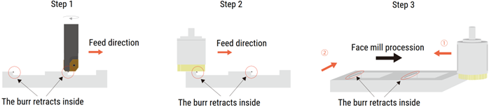
- Step 1: After precision machining, burrs will typically form on the side of the slit.
- Step 2: As you continue to process in one direction, these burrs may shift and accumulate inside the slit.
- Step 3: To remove the burrs, position the fiber brushes to face the burrs directly (using direction ① or ②). Then, remove the burrs by reversing the direction of the brush.
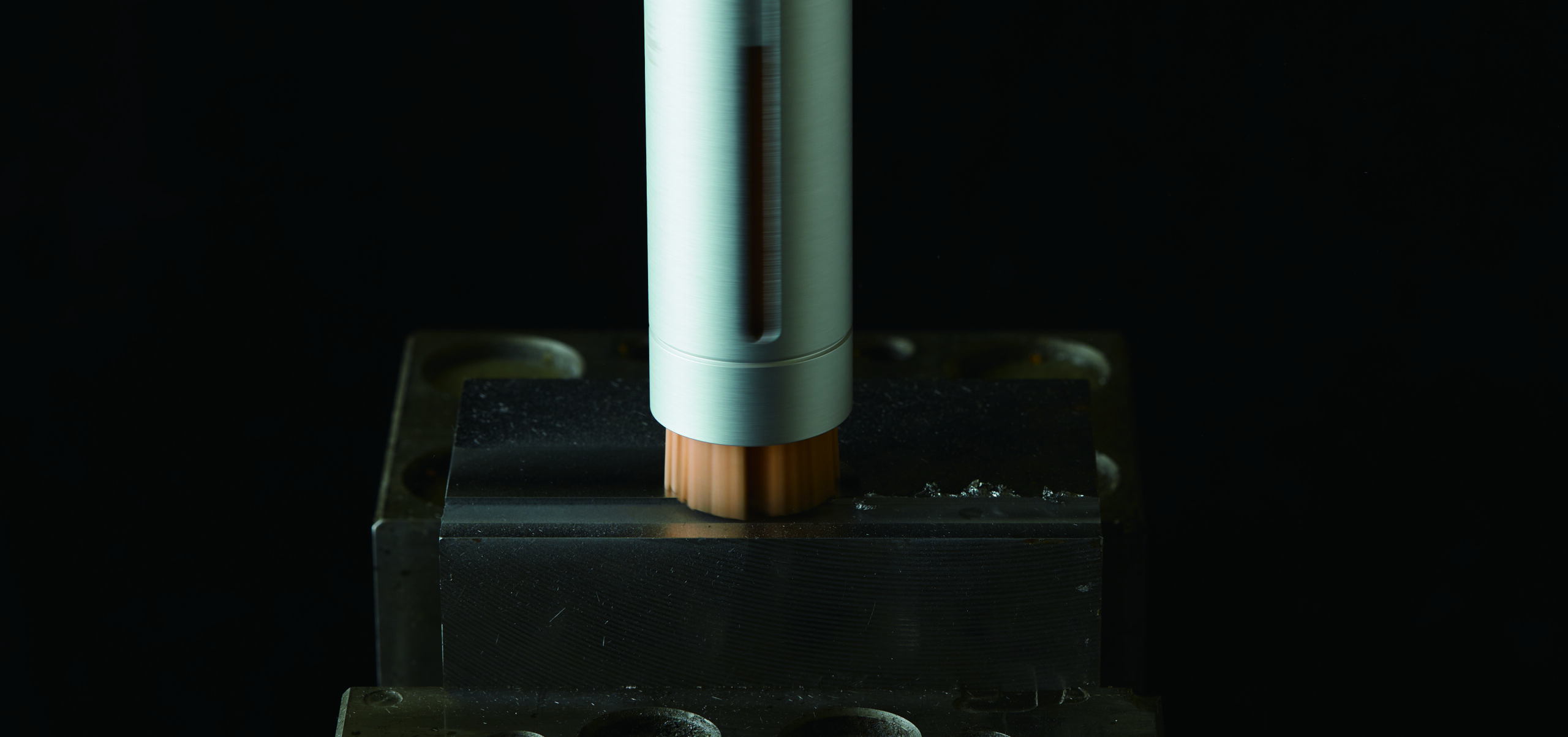
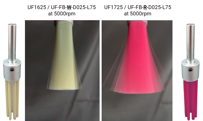
5. Versatile Surface Brush for Efficient Cross-Hole Burr Removal
The surface brush can also function as a cross-hole brush, leveraging centrifugal force during rotation to expand and efficiently remove fine burrs from the inner surfaces of cylinders.
To use this feature, simply attach the appropriate shank as specified by the ØDS parameter in the product specifications. The image illustrates how the #1200 and #1000 φ25 surface brushes expand at 5000 RPM. The #1200 brush is more flexible compared to the #1000 brush, allowing for greater expansion.
It is recommended to start with the #1200 brush. If burrs remain, switching to the #1000 brush is advisable.
Please note that the #1200 brush is more susceptible to breakage than other grits. To prevent damage, always insert the brush into the hole before starting rotation and stop the rotation before removing it from the hole.
Surface brush safety Precautions:
- Ensure that the tool operates within the recommended maximum rotational speed to prevent brush damage.
- The tool should be used within the cylinder or workpiece area to avoid unnecessary wear on the brush.
- It is suitable for processing centered holes and cross holes that are properly aligned.
- When installing the tool, ensure that the shank is gripped by at least 30mm. Failure to do so may cause the tool to detach due to vibrations, posing a risk of serious injury, including loss of sight.
- Use a chuck that matches the shank diameter, and ensure the processing equipment can control the rotational speed.
Surface Brush Safety Instructions:
Please adhere strictly to the instructions provided in this guide. Using the product in a manner not specified here may result in serious injury or even fatality.
CAUTION:
The use of this product carries a risk of serious injury, including eye injury or blindness, if the product detaches from the equipment, if bristles break off, or if workpieces fracture. Particles such as fragments, debris, and burrs generated during processing can penetrate the eyes or skin, leading to serious harm. Dust from the process can damage lungs, irritate the skin, and cause allergic reactions.
If you detect any vibration or other unusual occurrences during use, stop immediately. Continuing to use the product under such conditions increases the risk of it detaching, breaking off bristles, or causing workpieces to break, potentially leading to severe injury.
Exceeding the recommended rotational speed can also cause detachment, bristle breakage, or workpiece fractures, posing serious risks to the operator. Extended machining at a constant point can cause the tool tip to overheat, increasing the likelihood of bristle detachment or breakage. To avoid this, adjust processing times to prevent overheating, and avoid direct contact with the machined area with bare hands after use.
NOTE:
The situations described above also pose risks of damage to machining tools, jigs, and workpieces.
Operator Safety Measures:
Protective Gear: Always wear appropriate personal protective equipment, including safety goggles, masks, gloves, and hearing protection, to minimize injury risks during machining. Wear long-sleeved clothing that fully covers the skin, and secure cuffs and hems tightly.
Work Area Safety: Install barriers to prevent unauthorized personnel from entering the work area, and ensure that anyone present is wearing protective equipment. Take special care to keep children out of the work area. Keep the floor clean and free of debris, cutting particles, oil, water, and other substances to prevent slips or falls.
Fire Safety: This product can generate heat or sparks, potentially causing fires. Do not use it near flammable liquids or in explosive atmospheres. Implement appropriate fire prevention measures.
Handling Cutting Particles:
Processing with this product generates fragments and debris that may scatter. Use a dust collection system or similar method to capture these particles.
